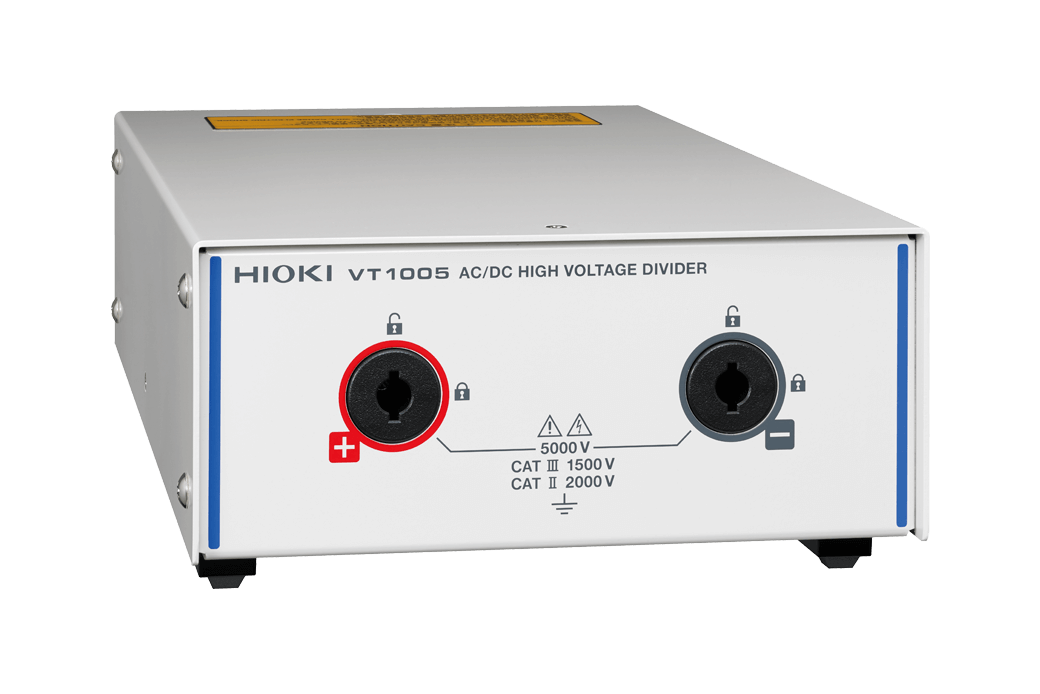
Safely Measure High Voltages up to 5000 V
Detect Efficiency Improvement Effects on the Order of 0.1%
Description
Inverters used in rail and power system applications convert high-voltage power. To measure the efficiency of such conversions, it’s necessary to measure voltages of 1000 V and above. The VT1005 divides voltages of up to 5000 V and outputs them to a power analyzer.In order to measure the efficiency of high-efficiency inverters with a high degree of precision, you need to be able to accurately measure power from DC to high frequencies. Thanks to its excellent frequency flatness, the VT1005 makes possible accurate measurement at frequencies ranging from the fundamental wave to switching-frequency components.
Key Features
- Max. Input 5000 V (*1)
2000 V CAT II
1500 V CAT III - Measurement Accuracy:
±0.08% (DC)
±0.04% (50/60 Hz)
±0.17% (50 kHz) - Frequency Flatness:
±0.1% Amplitude Band 200 kHz Typ.
±0.1° Phase Band 500 kHz Typ. (*2) - Measurement Band:
DC to 4 MHz (-3 dB) - Noise Resistance:
CMRR 80 dB Typ. (100 kHz)
Differential Input Method
- *1:±7100 V peak, no measurement category, anticipated transient overvoltage of 0 V
- *2:After phase correction by the power analyzer
Model No. (Order Code)
| VT1005 |
|---|
Specification
Accuracy guaranteed for 1 year
| Maximum rated voltage | 5000 V rms, ±7100 V peak (*1) |
|---|---|
| Maximum rated voltage (line-to-ground) |
No measurement category: 5000 V AC/DC (*2) Measurement category II: 2000 V AC/DC (*3) Measurement category III: 1500 V AC/DC (*4) |
| Voltage dividing ratio | 1000:1 |
| Measurement accuracy | ±0.08%(DC), ±0.04%(50/60 Hz), ±0.17% (50 kHz) |
| Frequency flatness |
Band where amplitude falls within ±0.1% range: 200 kHz (typical) Band where phase falls within ±0.1° range: 500 kHz (typical) (*5) |
| Measurement bandwidth | DC to 4 MHz (Amplitude and phase accuracy specified up to 1 MHz) |
| Common-mode voltage rejection ratio (CMRR) |
50 Hz/60 Hz: 90 dB(Typical) 100 kHz: 80 dB (Typical) |
| Measurement method | Differential input |
| Operating temperature and humidity range | -10°C to 50°C (14°F to 122°F), 80% RH or less (non-condensing) |
| Storage temperature and humidity range | −20°C to 60°C (-4°F to 140°F), 80% RH or less (non-condensing) |
| Standards | Safety: EN 61010 EMC: EN 61326 Class A |
| Power supply | 100 V to 240 V AC (50/60 Hz) |
| Dimensions and Weight | Approx. 195.0 mm (7.68 in) W × 83.2 mm (3.28 in) H × 346.0 mm (13.62 in) D mm Approx. 2.2 kg (77.6 oz.) |
| Included accessories | – L1050-01 Voltage Cord ×1 (1.6 m/ 5.25 ft) – L9217 Connection Cord ×1 (insulated BNC, 1.6 m/ 5.25 ft) – 9704 Conversion Adapter ×1 (insulated-female BNC-to-banana plug) – Power cord ×1 |
- *1:Within the frequency derating rangeNo measurement category: Applicable to the measurement of circuits that are not directly connected to the main power supply.EXAMPLE: Measurement on the secondary-side equipment from the socket outlet of fixed installation through a transformer, etc.
- *2:±7100 V peak, Anticipated transient overvoltage 0 V
- *3:Anticipated transient overvoltage 12000 V
- *4:Anticipated transient overvoltage 10000 V
- *5:After phase correction by the power analyzer
Measurement accuracy
| Frequency | Amplitude
±(% of reading + % of full scale) |
Phase |
|---|---|---|
| DC | 0.03% + 0.05% | – |
| DC < f < 30 Hz | 0.2% + 0.1% | ±0.1° |
| 30 Hz ≤ f < 45 Hz | 0.1% + 0.1% | ±0.1° |
| 45 Hz ≤ f ≤ 66 Hz | 0.02% + 0.02% | ±0.06° |
| 66 Hz < f ≤ 100 Hz | 0.1% + 0.02% | ±0.12° |
| 100 Hz < f ≤ 1 kHz | 0.1% + 0.02% | ±0.2° |
| 1 kHz < f ≤ 5 kHz | 0.15% + 0.02% | ±0.4° |
| 5 kHz < f ≤ 50 kHz | 0.15% + 0.02% | ±(0.08 × f kHZ)° |
| 50 kHz < f ≤ 100 kHz | 0.5% + 0.02% | ±(0.08 × f kHZ)° |
| 100 kHz < f ≤ 300 kHz | 1.5% + 0.5% | ±(0.08 × f kHZ)° |
| 300 kHz < f ≤ 1 MHz | 5.0% + 0.5% | ±(0.08 × f kHZ)° |
| Frequency band | 4 MHz(-3 dB Typical) | – |